Marking out and drilling the holes for the PCB board needing good precision. At this time it would be an idea to have a pedestal drill.
 Adding all the turrets
Populating the PCB board.

Adding the iron.
Now wiring, carefully does it.
The tubes: 2 x EL84's 3 x 12Ak7's and one EZ81.
The transformers: one 18 watt Power Transformer and one 18 watt output transformers
The cabinet being assembled.
I found it was very necessary to use an adhesive spray glue to keep the fabric from looking baggy.
Adding the piping. It was important to soften it first with a hairdryer as it was being stapled
to the baffle board.
All done and sounding very good. just a few finishing touches, the tremolo connection needs wiring and I am going to stain and varnish the wooden casing.
+
The little niggling problems that always arise after you think you have finished the job.
Okay, I admit it there were a couple of things that need to be remedied, which I will fix when I take the grill and amp off the cabinet for wood staining.
1) I ended the piping in the wrong place, it shold have been somewhere more discreet, ie the bottom of the cabinet.
2) I glued one of the upright struts before checking that the upper and lower back panels were flush with the main cabinet.
3) The metal corners don't fit flush. The bevel all around the cabinet must be increased.
All done now and I'm really pleased with the result. It sounds fantastic nice and loud.
I used a red stain and finishing oil, that I had left over from finishing a guitar,


 Adding all the turrets


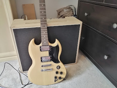


 Just the final tuning and harmonics adjustments to be made. The frets seem good but the strings are a bit high so they will need adjusting.


